Years ago, in a Gulfstream G450 recurrent, I was surprised by a simulator instructor’s preflight briefing because he added a requirement that I didn’t know about. He said, “I will need to see at least one approach and landing using the HUD.” I had long before learned to appreciate the head-up display (HUD) as a cockpit tool that made my life easier, and the requirement seemed as superficial as saying, “You will need to take regular breaths during this flight.” I got into the seat, lowered the HUD into position, and kept it there. About halfway through the 1.5-hr. sim session, the instructor said, “You’ve done enough with the HUD; you can put it away if you want to.” I left the HUD where it was. After the session I asked him about all this and he said, “Most of my clients prefer to fly without it.”
In the years since, I’ve noticed about half the pilots I was paired with in the G450 simulator used the HUD the way I did (all the time), and the rest used it sparingly. In the newer Gulfstream GVII aircraft, every pilot I’ve been paired with uses the HUD all the time. Why the difference?
In the older airplane, the conventional “heads down” view in the primary flight display (PFD) defaulted to what you would find in an airplane with a mechanical attitude director indicator (ADI) from 50 years ago. These ADIs present a horizon, an airplane symbol and a flight director using “vee bars,” so called because they were shaped like an inverted letter “V.” HUDs don’t use this symbology and going from one to the other can be confusing. (In the G450, the pilot can change the PFD to use HUD symbology, but few pilots did that.) In our GVII, the pilot has no choice: The PFD mirrors the HUD. I think that is the way things are going, so if you are not “one with the HUD” and your airplane has a HUD, it is time to get with the program.
Understanding a Conventional Primary Flight Display (PFD)

Early attitude indicators used mechanical gyroscopes to stabilize an artificial horizon that was calibrated on the ground to be wings level and aligned with an aircraft symbol. That symbol was drawn or mechanically placed in the display, so you could be assured that it truly represented the aircraft. The artificial horizon, however, was forever suspect because it could drift or even tumble. Modern electronic PFDs share much in common with their mechanical ancestors: The aircraft symbol is tied to the aircraft structure and the horizon is set relative to the aircraft’s attitude on the ground.
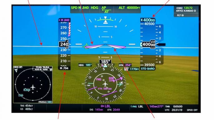
The photo of a conventional PFD is about as modern as they come, taken from a Cessna Citation Longitude, in level flight at 40,000 ft., Mach 0.794. Most pilots will be instantly comfortable with the display. The aircraft symbol is a white inverted “V” that is fixed in position. Flight director commands are presented by matching pink “vee bars” so that the pilot flies the fixed vee bars into the moving vee bars to satisfy flight director commands. The pitch of the aircraft is shown to be about 2 deg. above what pilots have come to call the horizon but is really a relative horizon. It is relative because placing the nose of the aircraft on this line will mean the aircraft is parallel to where it was on the ground, that is, it is a horizon relative to the ground. This PFD also shows a synthetic view of the terrain, and the actual horizon is shown about 5 deg. below the relative horizon.
Note that the aircraft symbol doesn’t point to where the aircraft is going, only where the nose is pointing. The aircraft’s pitch is above the relative horizon so as to maintain level flight.
Understanding a Typical HUD

Early HUDs were added to conventional avionics suites, requiring pilots to learn two separate symbologies. Avionics designers have realized having two presentations is confusing and are now using HUD symbology in the PFD.
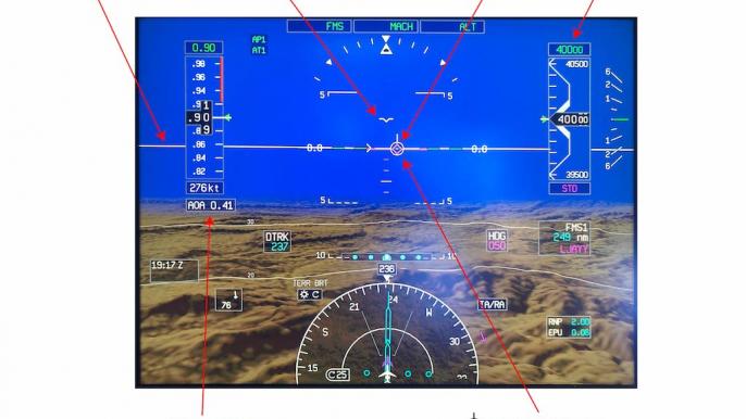
The photo of a PFD using HUD symbology is taken from a Gulfstream GVII-G500 in level flight at 40,000 ft., Mach 0.90. Most pilots will recognize much of the display but will struggle with what looks like a horizon and will search in vain for an aircraft symbol. “Where is the nose of the aircraft?” they will ask. It is shown as a flat “V” with wings and is called a boresight by Gulfstream but goes by other names by other manufacturers. Like the aircraft symbol on a conventional PFD, it does show where the aircraft is pointed. But that is no longer the pilot’s primary focus. “Where is the horizon?” is the next question. It is below you, as shown by the synthetically drawn terrain. Once again, that is of lesser importance when flying using HUD symbology.
The pilot’s primary focus is no longer where the aircraft is pointed, but where it is going. That is represented by the flight path vector (FPV) and is drawn as a circle with small wings and a tail. The white horizontal line can be thought of as a horizon that has been adjusted to consider the altitude of the aircraft, as if the earth’s diameter has been increased. In some HUDs it is called a zero pitch reference line. You maintain level flight by placing the FPV on the zero pitch reference line.
What a HUD Gives You

A common complaint of users new to HUDs is information overload: “What am I supposed to be looking at?” You will hear the same thing from nonpilots visiting a cockpit for the first time: “How do you keep track of everything all at once?” The answer is the same for both questions: With training you realize what you need to look at and when you need to look at it.
If you are flying a pilot-friendly aircraft, you know the attitude indicator is in front of you, to the left is airspeed, to the right is altitude, and below that is a heading reference. This layout is continued in the HUD, but your eyes have shorter distances to travel. The primary advantage is that all this information is presented to you where your eyes need to be for takeoff and landing: outside.
The video combines what the pilot is looking at “heads up” through a HUD during takeoff with the “heads down” view shown below. With the HUD, the pilot’s eyes never leave the view outside.
Adding an Enhanced Flight Vision System (EFVS)

The HUD makes takeoff and landing easier--no doubt about it. But does it allow you to land at lower visibility? No, not unless you pair it with an enhanced flight vision system (EFVS), also known as an enhanced vision system (EVS). Then the answer becomes yes, depending on where you are flying, how low you intend to go and what authorizations you have.
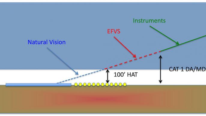
The U.S. rules are given in FAR Part 91.176 and are further explained in Advisory Circular 90-106A. If you meet the requirements of Section (b) of that FAR, you can operate using an EFVS to 100 ft. above the touchdown zone elevation, at which point you must use what the regulations call “natural vision” to complete the approach and landing. If you are operating under Part 91K, 121 or 135, you will need a management or operations specification. If you meet the requirements of Section (a) of that FAR, you can operate using an EFVS to touchdown and rollout. You will also need a letter of authorization, management specification or operations specification. AC 90-106A lists 1,000 RVR (runway visual range) as an adequate flight visibility and authorizations are normally written with this as a minimum.
International rules are given in International Civil Aviation Organization (ICAO) Document 9365, Appendix G, and are similar to the U.S. rules with the notable addition of RVR reduction tables. A 1,200 RVR minimum, for example, may be reduced to 800 RVR when using EFVS. Most foreign countries, however, require a specific approval to conduct EFVS operations. You will need to check that country’s aeronautical information publication to be sure.
Editor’s Note: A next article by James Albright will give tips about learning how to use a HUD.


